Mounting and Cooling
The microFLUX 2MPi offers 6x M2 mounting holes to secure the unit to your cooling solution/aircraft. Ensure you use a tightening torque appropriate to the fastener and mounting material you are using. The mounting holes accommodate a head diameter/ washer diameter of 4 mm [0.15in].
The correct installation of the microFLUX 2MPi relies heavily on ensuring proper isolation. The bare board contains numerous exposed contacts, including a significant area of exposed live copper. This particular region serves to enhance thermal transfer, thus, establishing adequate electrical isolation for the board is imperative to prevent potentially hazardous short circuits. As a rule of thumb, there must be a minimum 0.6 mm [0.023 in] air gap between exposed contacts and any conductive materials in the mounting assembly. All direct contacts to the unit, especially the thermal interface materials (TIM), must be electrically insulative. Keep-out zones for the microFLUX 2MPi can be found in the CAD available from our datasheet.
The microFLUX 2MPi board should not be placed under high stress and torsional loads. The microFLUX 2MPi should be mounted in a floating arrangement. Standoffs or a sled that raises the unit should be used to create the required air gap between the electronics and the mounting surface, as well as to allow airflow for passive cooling to take place. The diameter of the standoffs cannot exceed 5 mm [0.19in] and should be at least 3.5 mm [0.13in] tall to allow sufficient clearance between the components and the mounting surface. See the diagram below for details.
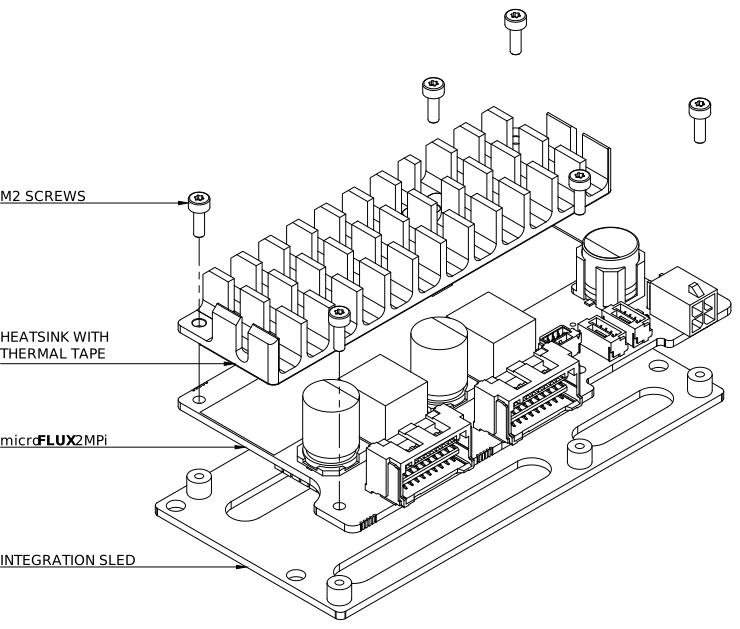
The displayed integration sled and heatsink are optional accessories for the microFLUX 2MPi. These accessories will greatly reduce the airflow required to keep the unit cool and will assist in getting your vehicle operational sooner.
The heatsink integration kit includes - 1x heatsink and 1x thermal tape solution, and the mounting sled integration kit includes - 1x mounting sled and 6x M2 socket head cap screws.
The heatsinks will come pre-applied with thermal tape. To install the heatsink, remove the plastic backing sheet, carefully position the heatsink and press it firmly into place. Take care to not damage components on the underside of the board when applying pressure to the heatsink.
Removal of thermal tape should be done using plastic tools to avoid scratching or otherwise damaging the electrical contacts of the board.
If you decide to purchase the microFLUX 2MPi standalone, we recommend using our integration designs as a reference for how you should mount and cool the unit. CAD files can be found at: http://hrgve.tech/uF-2MP_CAD.
If you decide that a heatsink is not required for your specifications, we do still recommend covering the exposed copper surface to protect against accidental contact and electrical connection. This can be achieved with any non-conductive material, such as polyimide tape or similar.
The microFLUX 2MPi is a bare-board smart power supply with exposed electrical connections. Contact with water or significant amounts of dust/particulate can result in unit failure. Ensure that the microFLUX 2MPi is mounted in a location with appropriate environmental protection to reflect the vehicle’s operating conditions.
Cooling Considerations
The heat generating region on the microFLUX 2MPi are highlighted in the below drawing.
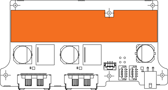
The microFLUX 2MPi has a particularly high power density, making effective cooling a challenge. To ensure the microFLUX 2MPi can operate continuously at the required current, you need a cooling solution that can effectively dissipate the thermal power from the unit to ambient. This specific area to cool is identifiable by the presence of the exposed copper thermal transfer pad. To find power dissipation and temperature limit calculations, please consult the PerformancePerformance section.
It is important to note that without any sort of heat-spreader solution to thermally connect components, the temperature sensors are thermally isolated from critical components and thus, may not provide accurate readings of the temperature of these components.