SH80 - BETA
This documentation contains a brief technical guide and information on the operation of SH80 electronic speed controllers.
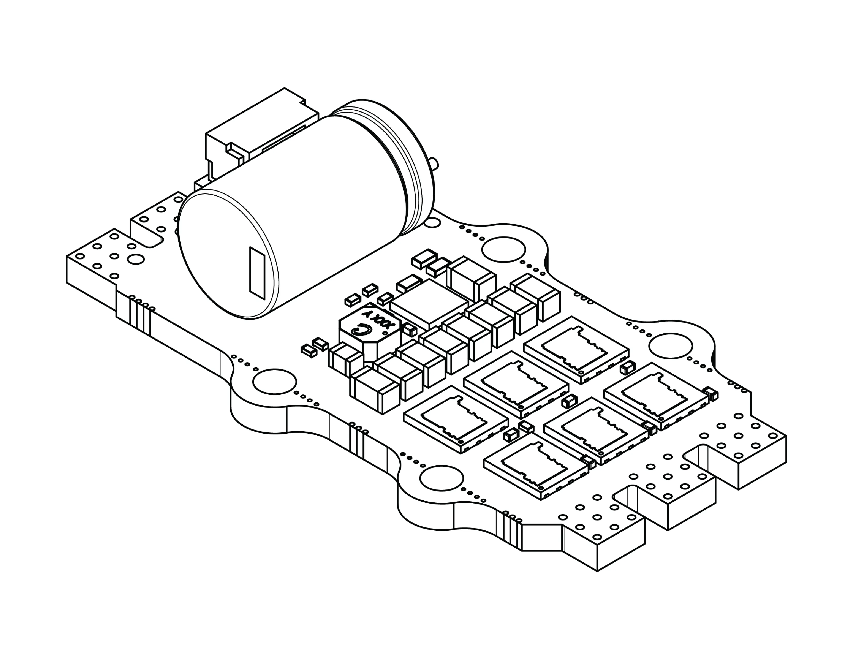
Features
The key features of the SH80 hardware and firmware:
- 80A Continuous Phase Current, 120A Burst Phase Current.
- DShot and Standard Servo PWM support.
- Trapezoidal motor control.
- Onboard capacitor.
- No Chinese components.
- Accurate telemetry measurement over full operation range.
- Pre-soldered signal and telemetry connector.
- Low-power sleep state.
- Highly configurable over multiple interfaces.
- Self-health checking with hardware self-tests on start-up.
- Self-correcting memory, use of onboard backups and error-correcting codes.
- Counterfeit protection.
The following checklists are a helpful starting point for new systems.
1. Wiring
Wiring-specific checks to perform when starting with a new system.
Ensure Bus Motor and Motor Phases are connected. It is recommended to keep the input lead length to a maximum of 20 cm [7.9 in].
Ensure DShot or PWM control signals are connected.
If using a tethered system or power supply for input power, confirm the AFW setting is disabled. This turns off the regenerative braking response and removes the risk of overvoltage events.
Pinout
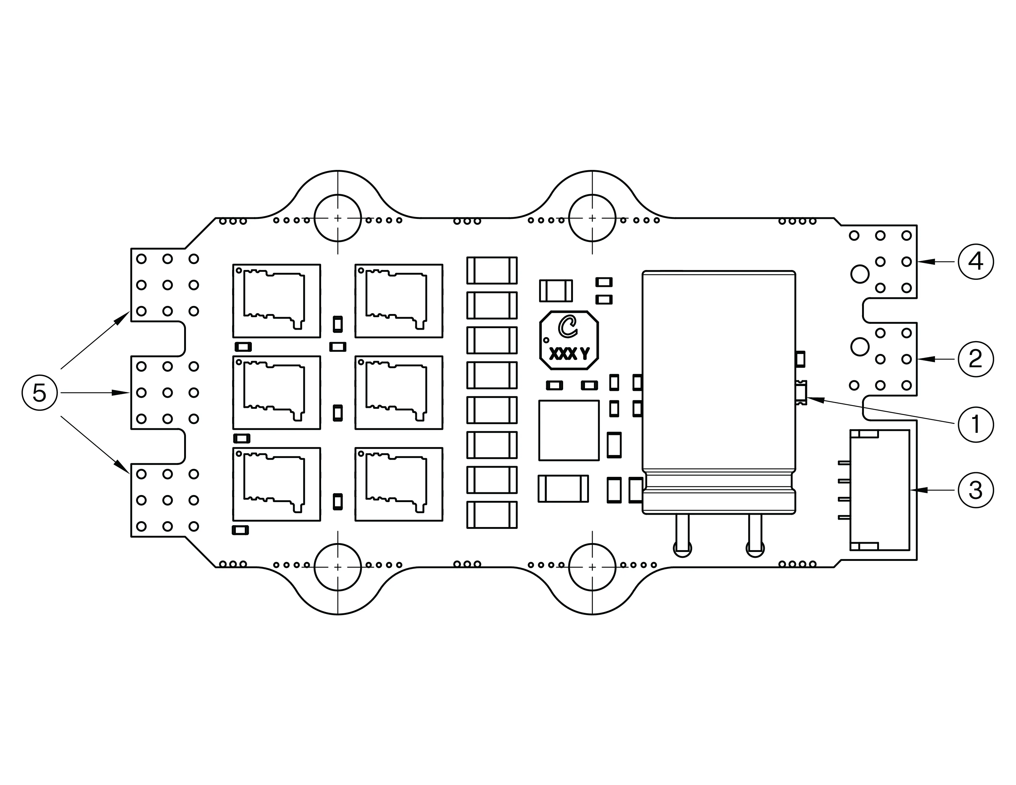
The pinout for SH80 units can be found below. The ports are referencing the image above.
Port Number | Description |
|---|---|
1 | Status LED |
2 | Main bus positive (+) |
3 | Signal and telemetry connector |
4 | Main bus negative (-) |
5 | Motor phase cables (A,B,C) |
Signal and Telemetry Port
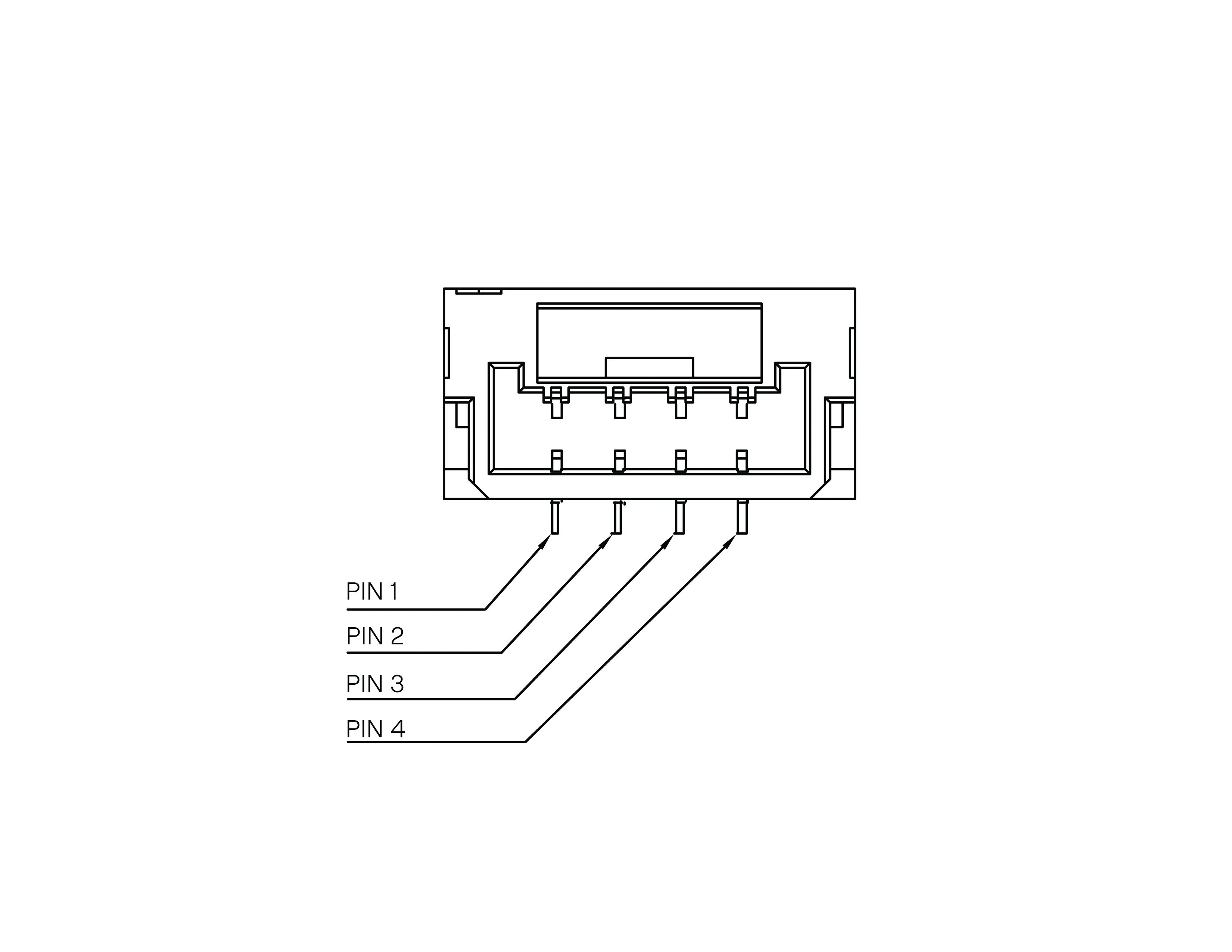
Pin Number | Purpose |
|---|---|
1 | Serial Signal (DShot/PWM) |
2 | Serial Telemetry |
3 | Auxiliary Pin |
4 | Ground |
2. Configuration
The SH80 can be configured using the Hargrave Configurator tool.
It is important to configure the Motor KV and Pole Pair parameters. Further settings regarding protection mechanism, auxiliary pin function and signal & telemetry are also available to configure. Please reach out to the Hargrave Team for specific advice on any parameters.
More information on the configurator can be found here:
3. Mounting
Mounting checks that should be performed with a new system.
Ensure the motor controller is mounted securely to the vehicle.
Ensure cables are externally strain-relieved for long term reliability.
The correct installation of the SH80 relies heavily on ensuring proper isolation as the bare board contains numerous exposed contacts. The large area of exposed live copper opposite the MOSFETs serves to enhance thermal transfer for the inverter bridge. Establishing adequate electrical isolation for the board is imperative to prevent potentially hazardous short circuits. As a rule of thumb, there must be minimum 0.6 mm [0.023 in] air gap between exposed contacts and any conductive materials in the mounting assembly. All direct contacts to the unit, especially the thermal interface materials (TIM), must be electrically insulating.
The SH80 is a bare-board motor controller with exposed electrical connections. Contact with water or significant amounts of dust/particulate can result in unit failure. Ensure that the SH80 is mounted in a location with appropriate environmental protection to reflect your vehicle's operating conditions.
4. Cooling
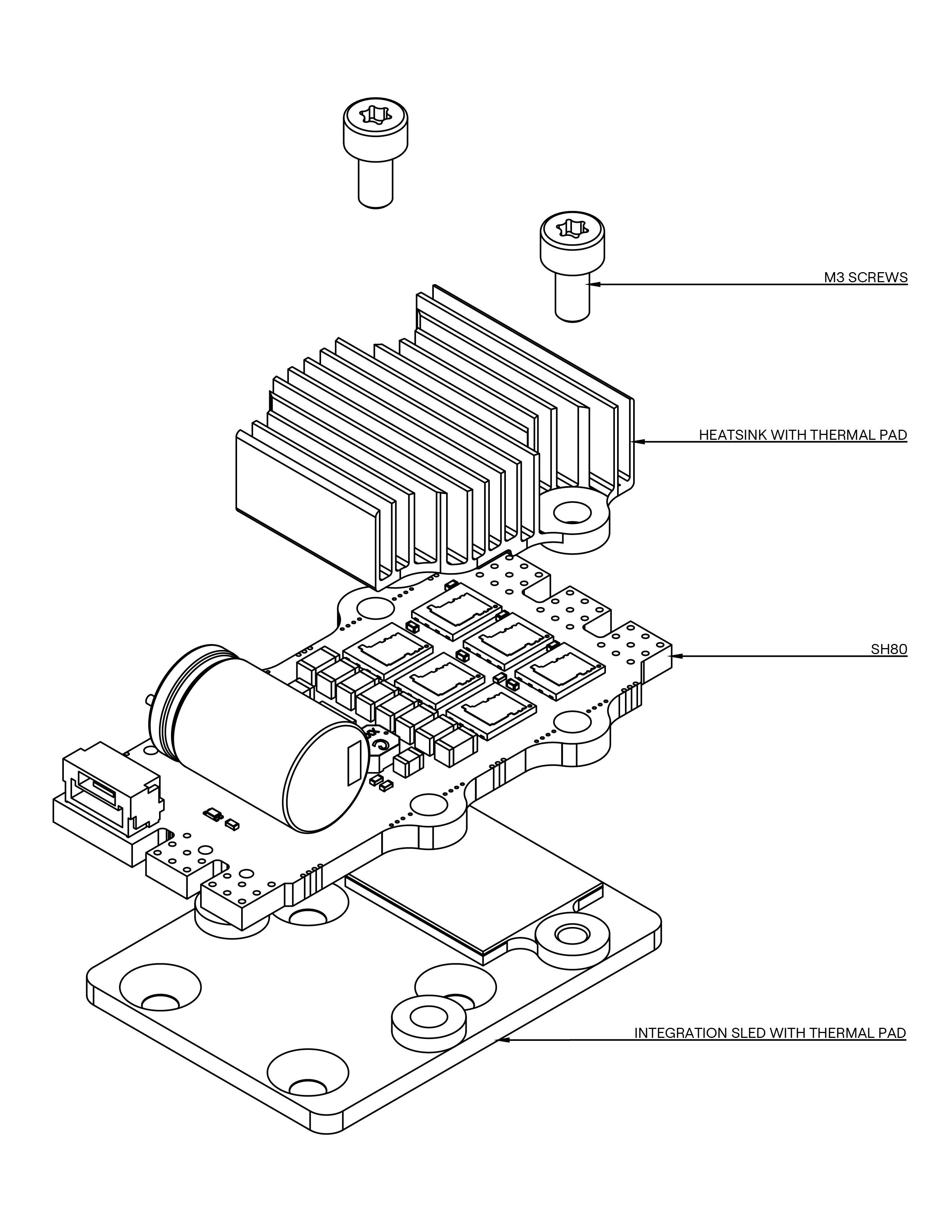
The SH80 has been designed to easily integrate with a cooling solution. All Beta unit kits are provided with a mounting package consisting of an Integration Plate and a Heatsink. A thermal pad comes pre-applied with both pieces, and the appropriate M3 screws are included.
- Ensure the integration plate is screwed to the vehicle first, with the appropriate countersunk screws. It can also be attached using an adhesive.
- Remove the protective plastic layer from the thermal pad on both sides.
- Sandwich the ESC between the plate and the heatsink, aligning the 2 holes through all 3 pieces.
- Tighten the M3 screws until finger tight. A maximum of 1Nm is recommended.
If the SH80 is being integrated into a custom cooling solution, or mounted without a heatsink, the mounting ears can be broken off for a smaller footprint. Use an appropriate wide plier to grip and break off the tab.
It is important to note that without a heatsink, the MOSFETs will be the thermal limiting factor for the SH80. With a heatsink added, the electrolytic capacitor becomes the limiting factor. If more performance is required, an additional capacitor can be soldered onto the input leads.
5. Communications
The communication checks that should be performed on a new system.
The SH80 can only be controlled over DShot/PWM. Ensure a valid control signal is being provided.
Set the motor pole pairs setting according to the motor connected, such that mechanical RPM is reported (rather than electrical RPM).
6. Protection Systems
The primary protection systems that are available on the SH80, along with default behaviour. Activation of protection may cause unexpected system responses, which can affect a vehicle in flight. Check that the below behaviours are expected, and modify them as required for the application.
Over-temperature is activated when the temperature within the drive exceeds the set limit. The default behaviour is to ramp the output duty to 50%. The normal drive will resume once the temperature is reduced below the limit. The MCU and Bridge each have their own temperature sensor with respective temperature limits that can be configured.
Signal timeout is activated when no valid signal is received within 500 ms. The drive will shut down. The drive will be resumed once a valid signal is returned and the throttle is 0%.
Require zero throttle can be overridden if the signal is lost and returned. Toggle this option to automatically disable the zero throttle setpoint requirement upon signal loss and re-establishment. When enabled, the ESC requires a 0% throttle signal to re-arm after signal loss. This requirement is always present if operating with PWM.
Overvoltage is triggered when the overvoltage threshold is passed on the bus/input voltage. The normal drive will resume once the voltage settles below the limit. The default response will slowly limit the output power until the event clears.
Undervoltage is triggered when the undervoltage threshold is passed on the bus voltage. The normal drive will resume once the voltage settles above the limit. The default response is to perform no actions.
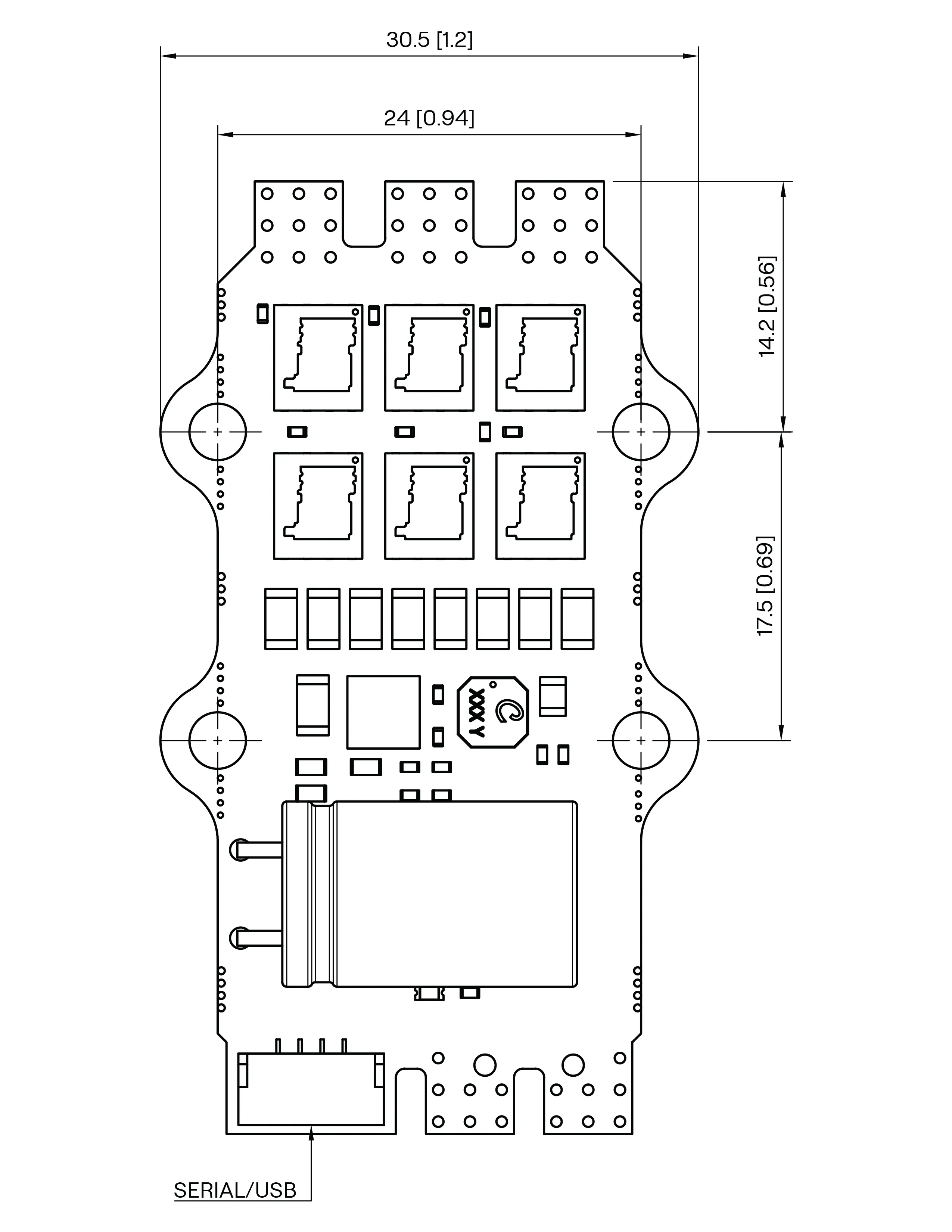
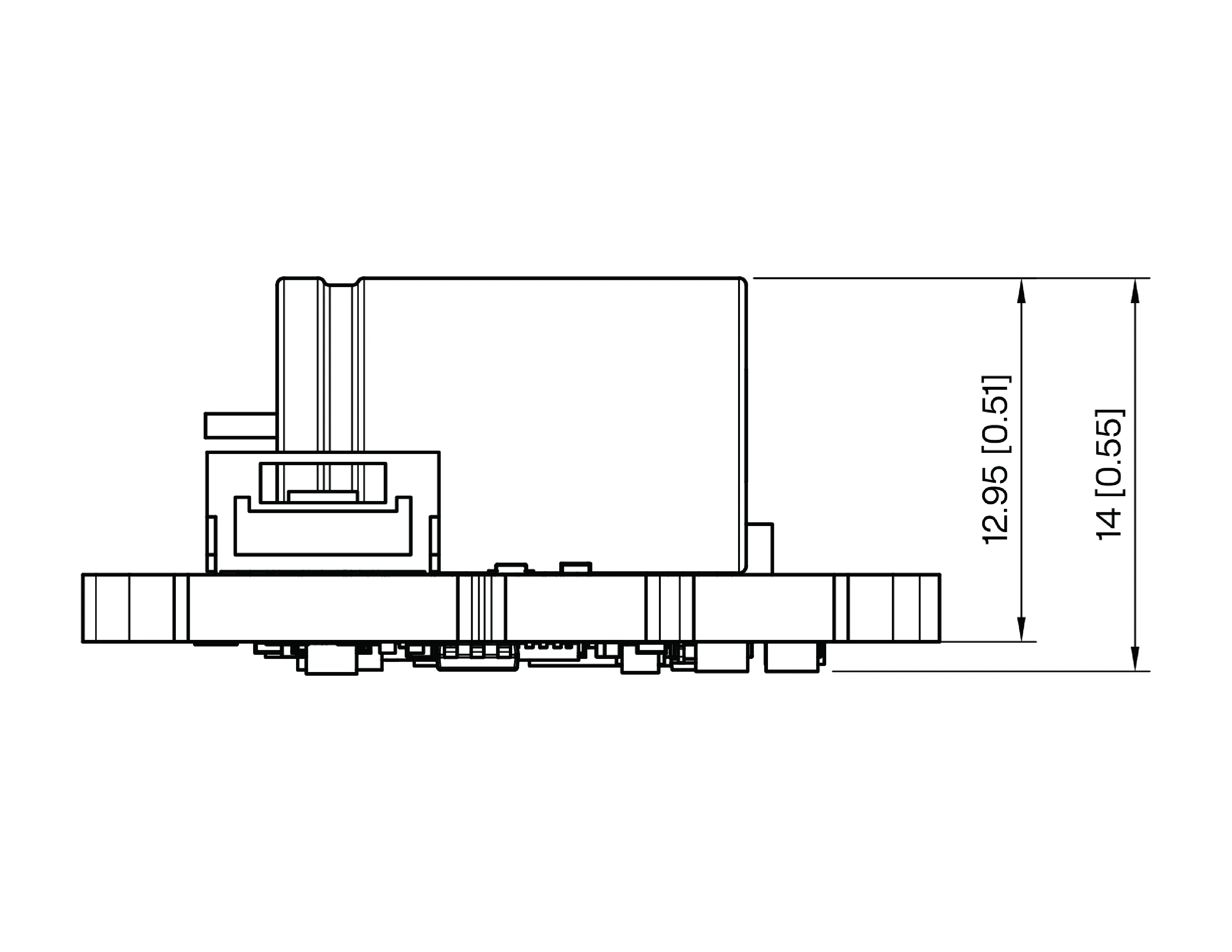
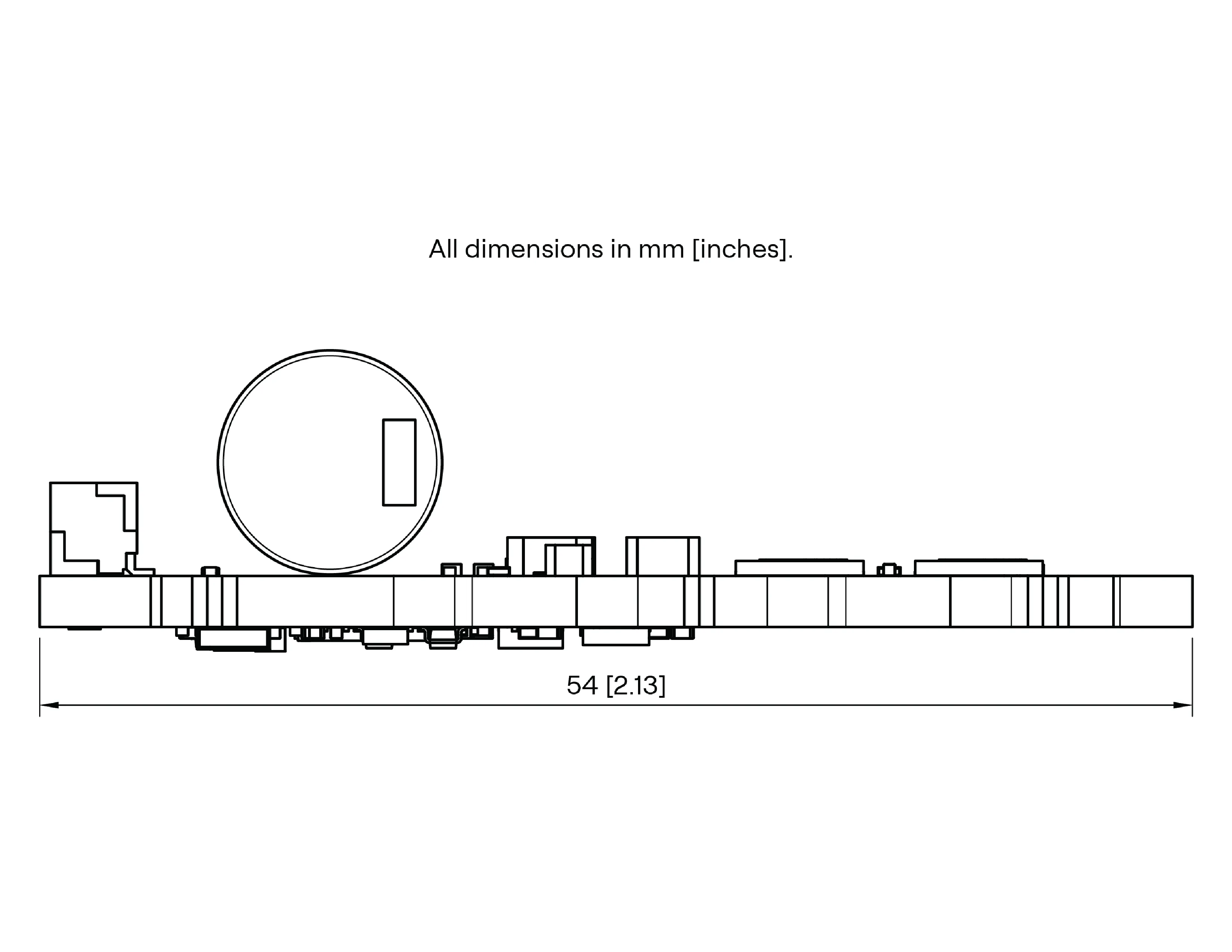
7. Dimensions and CAD
Please find the CAD for the SH80 at the link below:
Support
We pride ourselves on industry-leading support. A support engineer is available for all questions and assistance. Contact details can be found below.