ARINC Basic Guide
This basic guide is intended for users that are unfamiliar with the ARINC 825 specification and wish to implement the Hargrave ARINC 825 message set in a CAN 2.0B system.
This basic guide will cover the basic CAN ID structure of messages and provide details on how to control, configure and read telemetry from a device.
CAN Arbitration ID
Unless stated otherwise, the correct CAN ID for a message can be generated by left bit-shifting the SID and bitwise OR-ing that with the base CAN ID: 0xXXXXXXXX | (SID << 2) For a message with a base CAN ID of 0x12345600, the CAN ID for SID 1 would be 0x12345604.

CAN Bus Activation
The ARINC 825 sub-system on the device will only begin operating once traffic is detected on the CAN bus. The first message a device receives after powering on will not be processed, therefore it will not be responded to.
It is recommended for the system to send a Periodic Health Status Message (PHSM) at 1Hz, documentation for the PHSM can be found below. For bus activation purposes this message can simply be the following CAN packet:
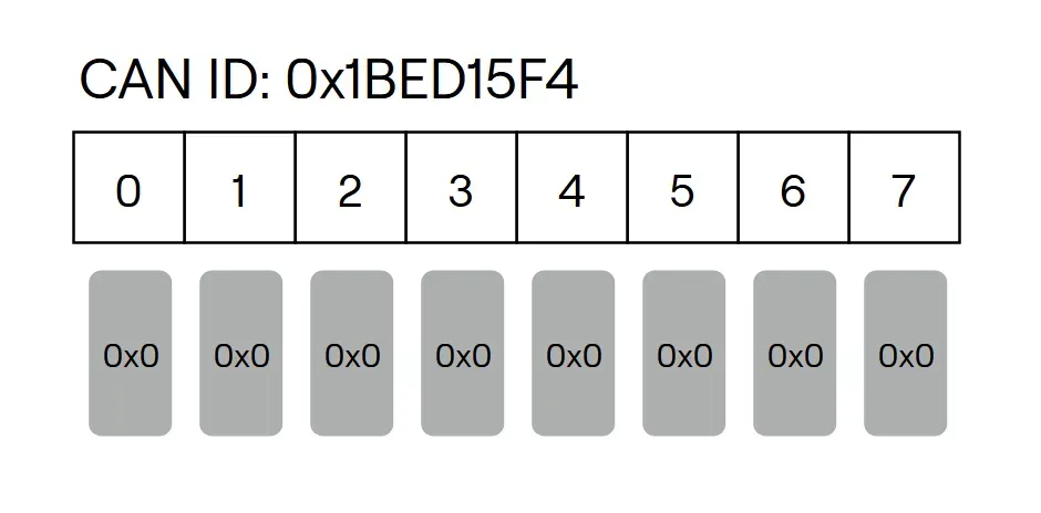
CAN ID
0x1BED15F4
Payload
Bytes | Datatype | Content |
|---|---|---|
0-7 | 0x0 | Payload can be all 0. |
Control and Telemetry
Details about the control and telemetry message set can be found at the below link:
Periodic Health Status Message (PHSM)
The device will broadcast a Periodic Health Status Message (PHSM) at a default rate of 1Hz, this rate is configurable. The PHSM acts as a sign of life from a node on the bus as well as informing the bus of CAN errors.
CAN ID
The PHSM message CAN ID is: 0x1BED1600 | (SID << 2)
Where SID is the SID of the device sending the message.
For SID 1 the CAN ID is: 0x1BED1604
Payload
Bytes | Datatype | Content |
|---|---|---|
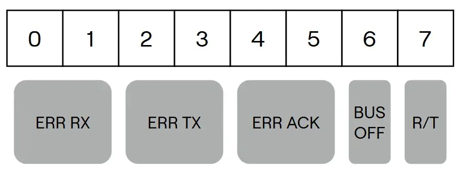
0-1 | UINT16 | ERR RX: Total detected receive errors since boot. Resets to 0 upon counter overflow. |
2-3 | UINT16 | ERR TX: Total detected transmit errors since boot. Resets to 0 upon counter overflow. |
4-5 | UINT16 | ERR ACK: Total detected acknowledgement errors since boot. Resets to 0 upon counter overflow. |
6 | UINT8 | Total detected bus off errors since boot. Resets to 0 upon counter overflow. |
7 | 4-bit bit field + 4-bit bit field | R/T: Receive/Transmit error states as defined in the ARINC specification. A value of 0x02 in each bitfield indicates nominal operation. |
Hargrave Protocol Tunnel
A series of messages have been implemented to allow communication with the Hargrave Configurator, this allows for a more convenient and more reliable configuration and firmware updating experience. These messages have the following CAN IDs:
Request: 0x1BFD1600 | (SID << 2)
Response: 0x1BF91600 | (SID << 2)
Node Services
The below functionality can be performed over ARINC using the Hargrave Configurator via SLCAN or MAVLINK.
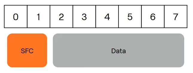
A variety of ‘Node Services’ have been implemented to perform configuration and non-control operations. The CAN ID does not change between the different node services, however the request and response CAN IDs are different. Node services are distinguished by a Service Function Code (SFC) in the CAN payload as shown below.
Requests are sent by the system and the device will send back a response.
Request CAN ID - 0x13FC1600 | (SID << 2)
The request CAN ID is: 0x13FC1600 | (SID << 2)
Where SID is the target device SID.
For SID 1 the CAN ID is: 0x13FC1604
Response CAN ID - 0x13F81600 | (SID << 2)
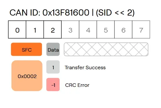
The response CAN ID is: 0x13F81600 | (SID << 2)
Where SID is the request target device SID.
For SID 1 the CAN ID is: 0x13F81604
Verifying Device Hardware
The Line Replaceable Unit (LRU) code can be requested from a node alongside other identifying information. This request can be used to verify the hardware of the device as the LRU code is the PCBA of the device truncated to 16-bits.
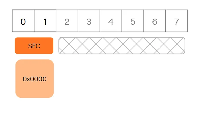
Request - 0x13FC1600 | (SID << 2)
The request payload is structured as follows:
Bytes | Datatype | Content |
|---|---|---|
0-1 | UINT16 | SFC: 0x0 |
Response - 0x13F81600 | (SID << 2)
The response payload is structured as follows:
Bytes | Datatype | Content |
|---|---|---|
0-1 | UINT16 | SFC: 0x0 |
2-3 | UINT16 | Profile ID |
4-5 | UINT16 | Profile Sub-ID |
6-7 | UINT16 | LRU Code |
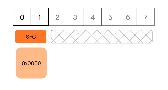
- Profile ID - A statically defined value intended to indicate the communication profile of the device, such as what messages it supports. Configurable via a device setting.
- Profile Sub-ID - The value to the right of the decimal place of the Profile ID. Configurable via a device setting.
- LRU Code - The line replaceable unit code of the device. Derived from the device PCBA.
Verifying Device Firmware
A request can be sent do a device to retrieve a 32-bit firmware build hash that can be used to verify which build of firmware is running on the device. The firmware build hashes can be found in the product documentation.
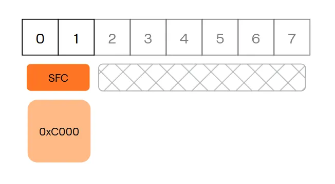
Request - 0x13FC1600 | (SID << 2)
The request payload is structured as follows:
Bytes | Datatype | Content |
|---|---|---|
0-1 | UINT16 | SFC: 0xC000 |
Response - 0x13F81600 | (SID << 2)
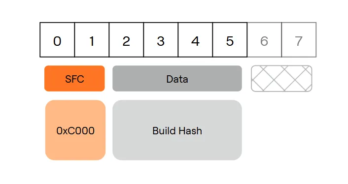
The response payload is structured as follows:
Bytes | Datatype | Content |
|---|---|---|
0-1 | UINT16 | SFC: 0xC000 |
2-5 | UINT32 | 32-bit firmware build hash |
Verifying Device Configuration
The device configuration can be verified by requesting a computed hash of the values of a given subset of settings. The following hash types are supported:
Hash Type | Settings Subset |
|---|---|
0x00 | All Settings |
0x01 | Group Settings: Settings that are typically kept the same between LRUs on a vehicle. |
0x02 | Protected Settings: Settings that are not individually configurable. If configured incorrectly, these settings could cause damage to your device. |
The process for verifying device configuration with settings hash values is as follows:
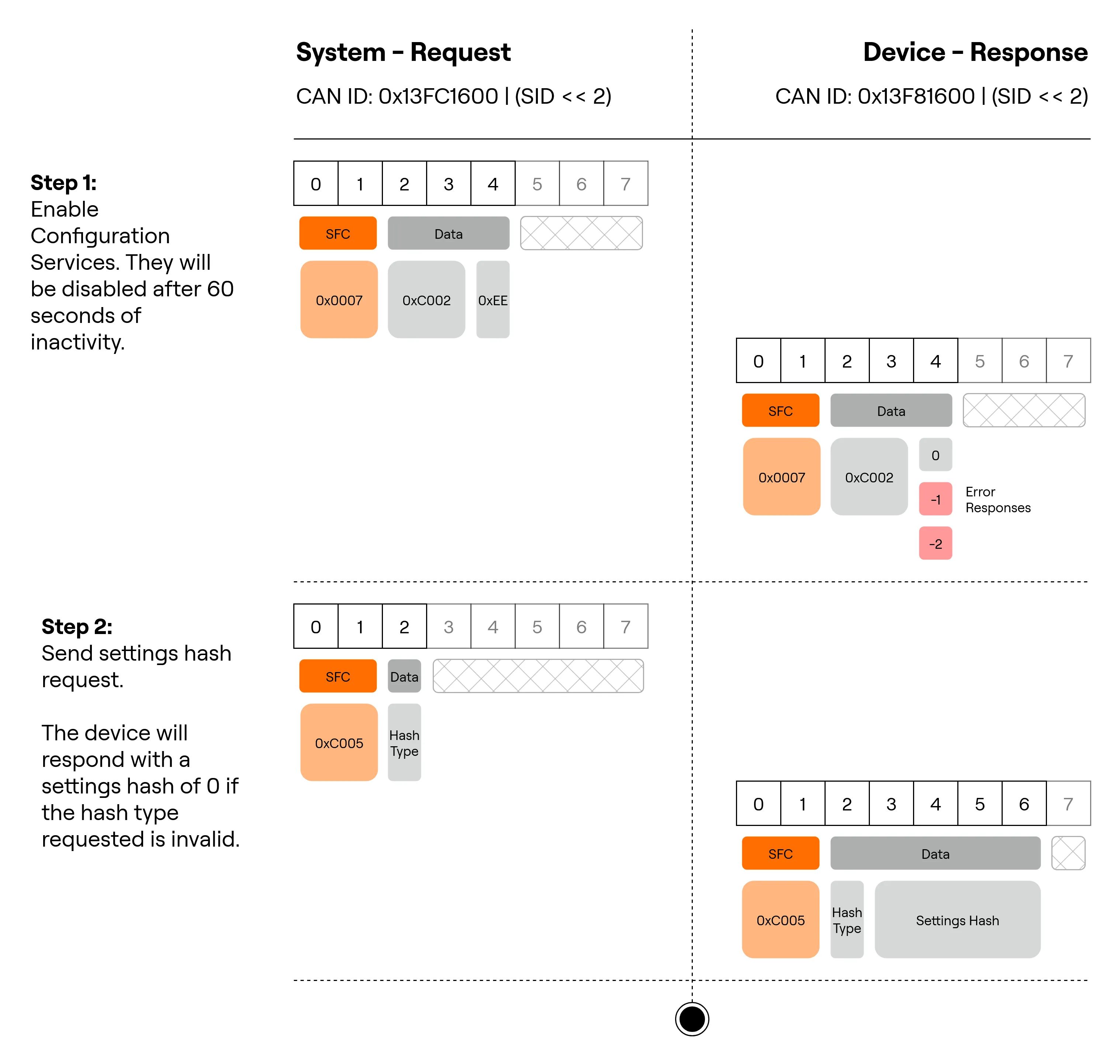
Configuring Device Settings
The Hargrave Configurator supports connecting to a device over ARINC 825 for device configuration.
Device settings can be changed and then saved to the device using ARINC node service messages. Setting IDs can be located in the product documentation.
Setting Types and Values
The following types are supported over node services:
Code | Type |
|---|---|
0x01 | BOOL |
0x02 | UINT8 |
0x03 | UINT16 |
0x04 | UINT32 |
0x09 | FLOAT32 |
Setting values in parameter handling node services are a maximum of 4 bytes and have the following memory representation for the above types:
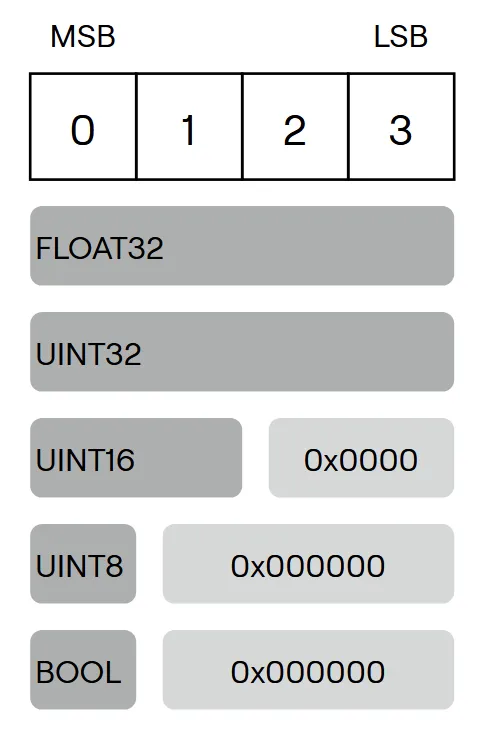
This type will be indicated with the term SETTING VALUE.
Configuration Procedure
The Hargrave ARINC-825 message set includes a series of messages for changing device settings. These configuration services must be unlocked before they can be used, all configuration services are unlocked together, the command to commit changed settings to device storage must be unlocked separately.
Multiple settings can be changed before the settings are saved to the device. It is not mandatory to retrieve the setting type and bounds before changing the setting, the device will ensure that the value in a settings set request is valid. Settings changes will not take effect until after the settings save command is sent and the device restarts.
If a command with an invalid setting ID is sent, the response payload will contain 0’s for setting ID and setting value field. If an invalid setting value is sent in a settings set request then the device will respond with the original unchanged setting value.
Below is an overview of the procedure to configure settings:
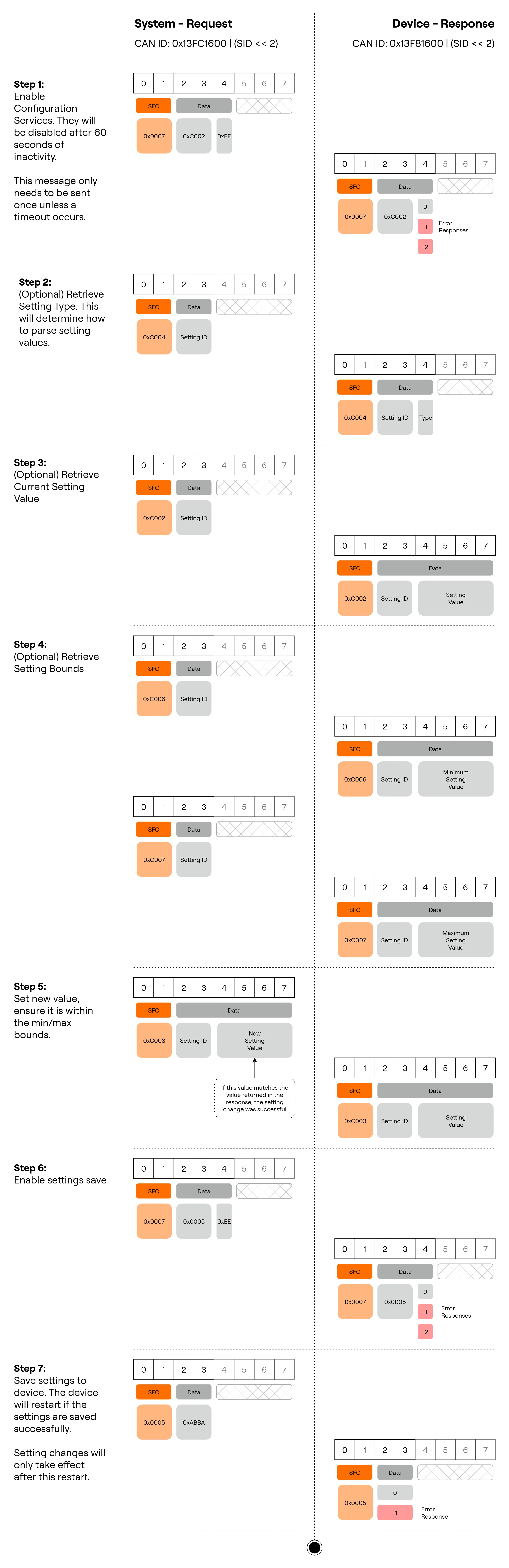
Resetting Device Settings
Follow the below process to reset the device configuration:
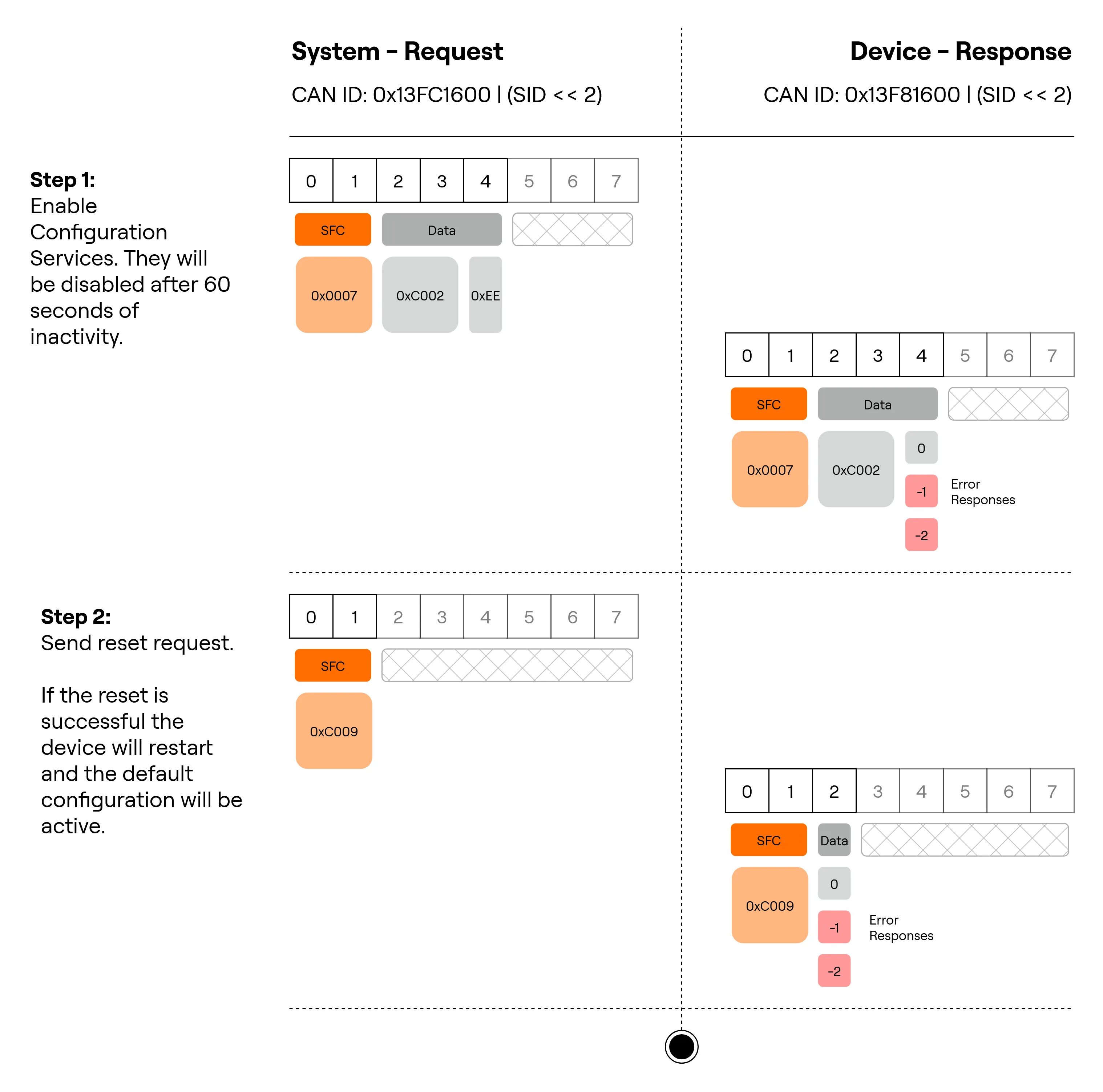
Restarting a Device
The Restart Service is used to request a device to reboot. Depending on the state the device is in (e.g. motor drive) it may reject a restart request.
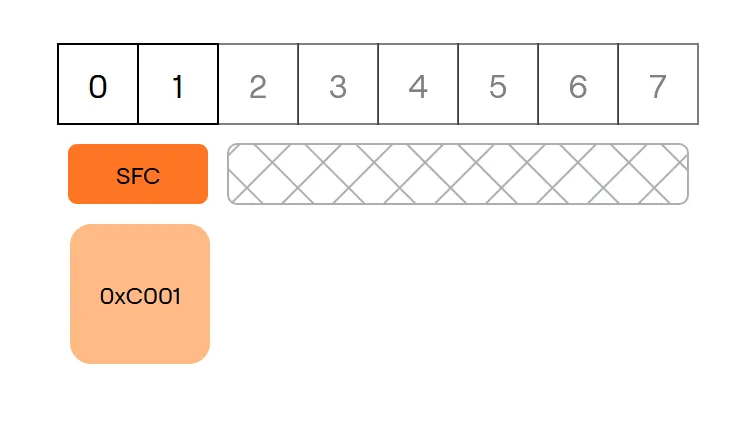
Request - 0x13FC1600
The request payload is structured as follows:
Bytes | Datatype | Content |
|---|---|---|
0-1 | UINT16 | SFC: 0xC001 |
Response - 0x13F81600
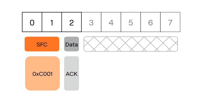
The response payload is structured as follows:
Bytes | Datatype | Content |
|---|---|---|
0-1 | UINT16 | SFC: 0xC001 |
2 | INT8 | ACK: 0 NACK: -1 |
Firmware Updating
Firmware updates can be performed over ARINC using the Hargrave Configurator via SLCAN or MAVLINK.
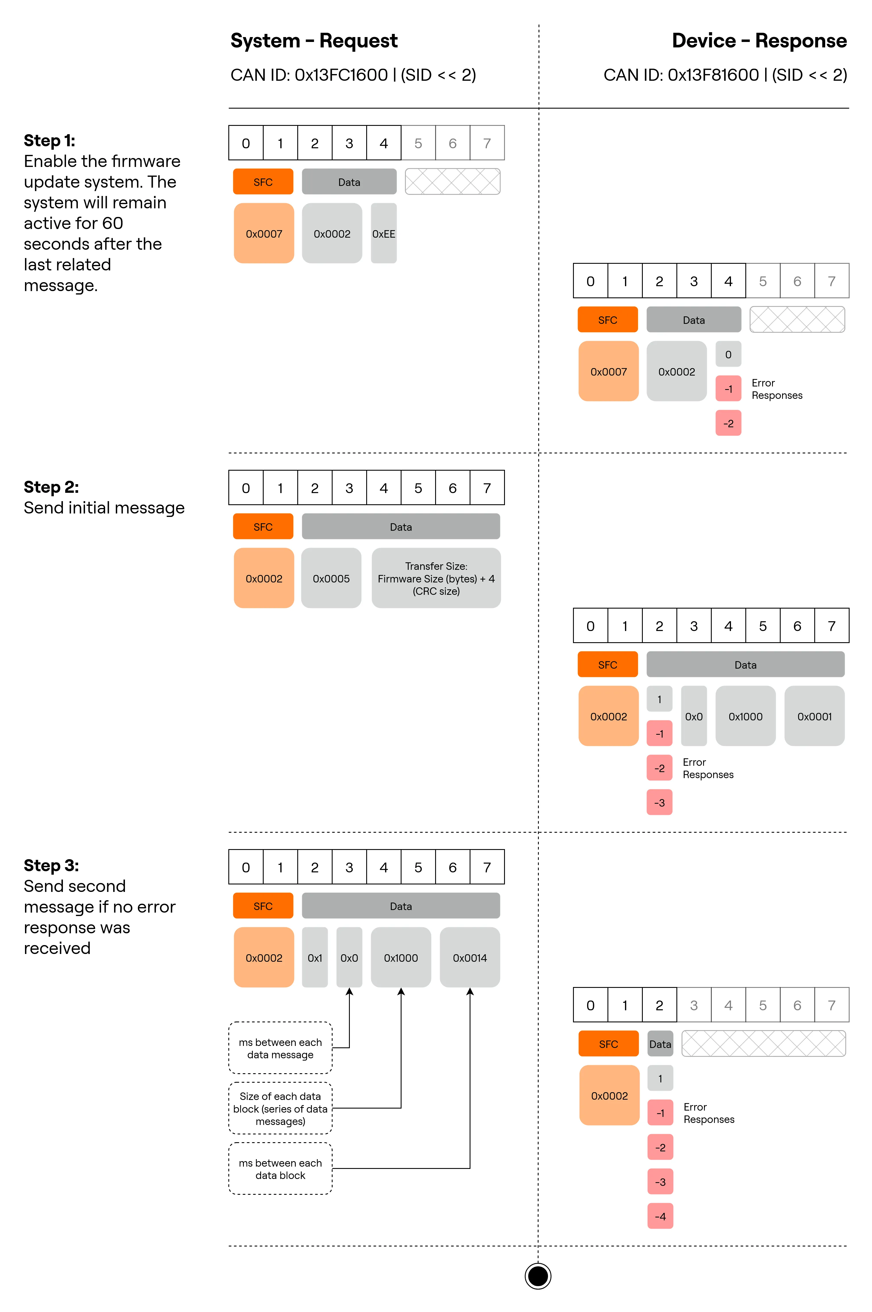
The firmware update process begins with enabling the firmware updating service, then a handshake to agree on the parameters for the transfer, the data messages, and then a final acknowledgement on if the transfer was successful.
Data messages have a different ID to regular node service messages:
Request ID: 0x13FD1600 | (SID << 2)
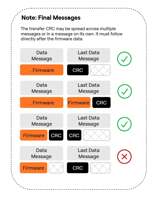
The total data payload to be sent will be the entire firmware payload + a 4-byte CRC32. The IEEE 802.3 Ethernet CRC32 is used, also known as the ISO-HDLC CRC. A test input of the character string ‘123456789’ should result in the output 0xCBF43926.
Step 1 - Initiate the firmware update
In step 3, the system sends a request which specifies the timing between each individual data message. This value should be adjusted based on system bandwidth and CAN bus integrity. The firmware update process will timeout after 50 times the the maximum of inter-message and inter-block spacing duration.
Step 2 - Send data payload
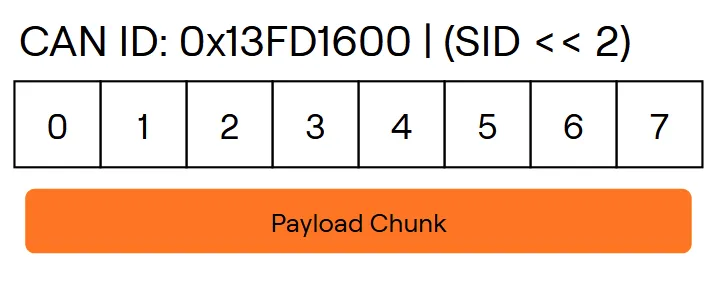
Data messages use a different CAN ID to the normal request messages. Data messages use the CAN ID of 0x13FD1600 | (SID << 2)
The payload (firmware file + 4-byte CRC32) must be sent as follows, immediately after the initialization sequence:
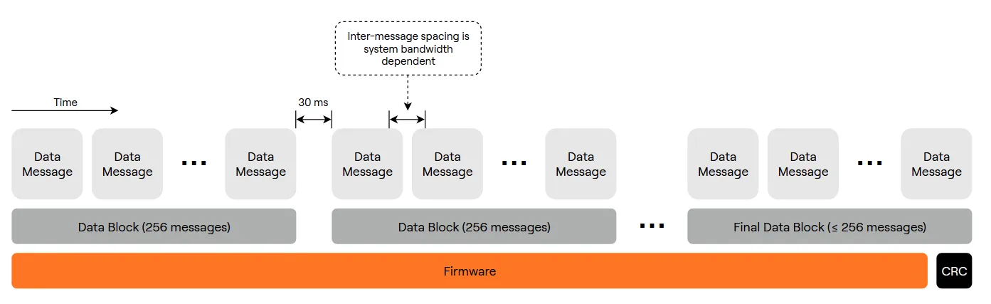
Each data message will be 8 bytes of the data payload. The final data messsage of the final data block may not be the full 8-byte length, and the final data block may not be the full 256 messages. Each data message is structured as follows:
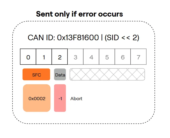
If an error occurs during the update process the device will respond with the following message, if this message is received the firmware update should be aborted and the device should be restarted.
The CRC should be sent immediately after the firmware data as follows:
Step 3 - Receive update result status
Once all data messages have been received the device will respond with the following message. If the ‘Transfer Success’ response is received the device should be restarted to update the firmware.