Control and Telemetry
Conventions
Percentage Representations
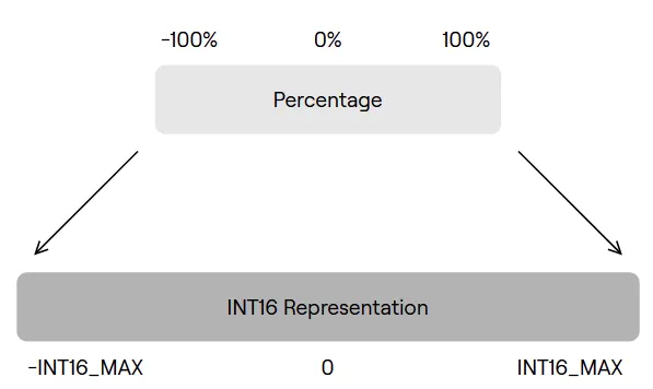
Payload values in percentages are mapped to the range of -INT16_MAX to INT16_MAX.
Group CID
A Group CID can be used to send a message to a group of 4 SIDs. The group CID is used in place of the device SID in broadcast messages.

Calculating Group CID
The group number, or group Controller Identifier (CID) for a device with a given SID (1-127) can be calculated as follows, please note the use of the floor division operator:

Example
A device with SID 8 will map to group 2 as demonstrated below:
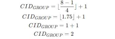
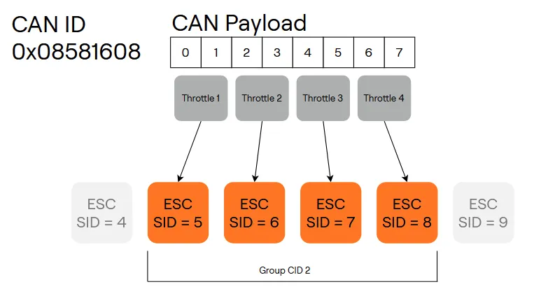
Group 2 will contain the following SIDs: [5, 6, 7, 8] or represented as the range: [5, 8].
Calculating Index within Group
The index of a device with a given SID within it’s group can be calculated as follows, ‘mod 4’ indicates the use of the modulo operator (often represented by the % in many programming languages):

Example
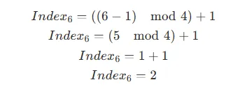
A device with SID 6 is in CID group 2 which contains the following range of [5, 8]. The index of SID 6 is calculated as, indexing is 1-based:
Group CID Diagram
The below diagram demonstrates the Group CID and Group Index relationship for SIDs 1-12, the pattern of groups and group indexes continues for higher SIDs.

Throttle Control
Throttle can be controlled with one of two methods, sending a throttle message to a singular ESC or broadcasting throttle to groups of 4 ESCs at a time. Throttle commands should be sent to each ESC at a minimum frequency of 1Hz. 100Hz is typical, but the frequency should be adjusted according to system requirements.
CAN ID | CFC | CID | Function Name | Sender | Payload | Description |
|---|---|---|---|---|---|---|
0x08581400 | (SID << 2) | 10 | SID | Direct Throttle | System | Signed 16bit Throttle | Throttle for specific controller based on SID. |
0x08581600 | (SID << 2) | 11 | Group CID | Broadcast Throttle | System | 4x Signed 16bit throttle | Throttle for a group of 4 controllers addressed by a group CID. |
Direct Throttle
A direct throttle command sends a singular throttle value to an individual motor controller on the bus.
CAN ID - 0x08581400 | (SID << 2)
The direct throttle message CAN ID is: 0x08581400 | (SID << 2)
Where SID is the target device SID.
For SID 1 the CAN ID is: 0x08581404
Advanced:
FID | CFC | CID |
|---|---|---|
Device (Default 11) | 10 | Device SID |
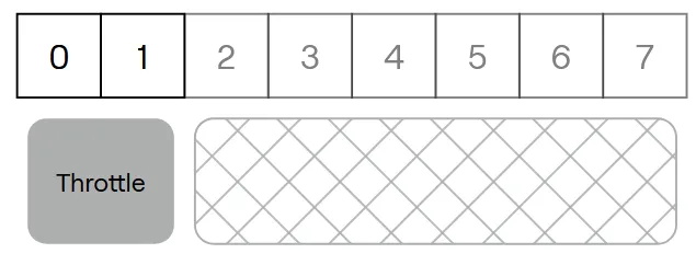
CAN Payload
The CAN payload is structured as follows:
Bytes | Datatype | Content |
|---|---|---|
0-1 | INT16 | Throttle Percentage Value (mapped to +/- INT16_MAX) |
Broadcast Throttle
A broadcast throttle sends 4 throttle values in a singular CAN frame to a group of up to 4 motor controllers. This can reduce bandwidth required for throttle commands compared to sending direct throttle commands to each ESC.
CAN ID - 0x08581600 | (Group CID << 2)
The CAN ID for the broadcast throttle uses the group CID instead of the SID as follows:
The direct throttle message CAN ID is: 0x08581600 | (Group CID << 2)
Where group CID is the target group CID.
For group CID 2 the CAN ID is: 0x08581608
Advanced:
FID | CFC | CID |
|---|---|---|
Device (Default 11) | 11 | Group CID |
CAN Payload
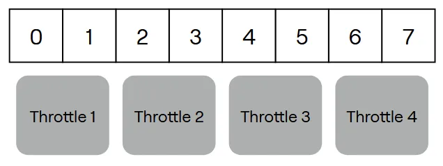
The CAN payload is structured as follows:
Bytes | Datatype | Content |
|---|---|---|
0-1 | INT16 | Throttle Percentage Value for group index 1 (mapped to +/- INT16_MAX) |
2-3 | INT16 | Throttle Percentage Value for group index 2 (mapped to +/- INT16_MAX) |
4-5 | INT16 | Throttle Percentage Value for group index 3 (mapped to +/- INT16_MAX) |
6-7 | INT16 | Throttle Percentage Value for group index 4 (mapped to +/- INT16_MAX) |
Example
The below diagram demonstrates how the broadcast throttle message operates with 4 ESCs with group CID 2:
Telemetry
Telemetry is broadcast over the following messages. The rate at which each message type is sent is configurable in device settings.
CAN ID | CFC | CID | Function Name | Sender | Payload | Description |
|---|---|---|---|---|---|---|
0x08586400 | (SID << 2) | 50 | SID | ESC Status 1 | ESC | 4x 16 bit Statuses | ESC Status Broadcast 1
|
0x08586600 | (SID << 2) | 51 | SID | ESC Status 2 | ESC | 4x 16 bit Statuses | ESC Status Broadcast 2
|
0x08586800 | (SID << 2) | 52 | SID | ESC Status 3 | ESC | 4x 16 bit Statuses | ESC Status Broadcast 3
|
ESC Status 1
The ESC Status 1 telemetry broadcast is sent by each ESC at a configurable frequency, default 10Hz.
CAN ID - 0x08586400 | (SID << 2)
The ESC Status 1 message CAN ID is: 0x08586400 | (SID << 2)
Where SID is the SID of the device sending the message.
For SID 1 the CAN ID is: 0x08586404
Advanced:
FID | CFC | CID |
|---|---|---|
Device (Default 11) | 50 | Device SID |
CAN Payload
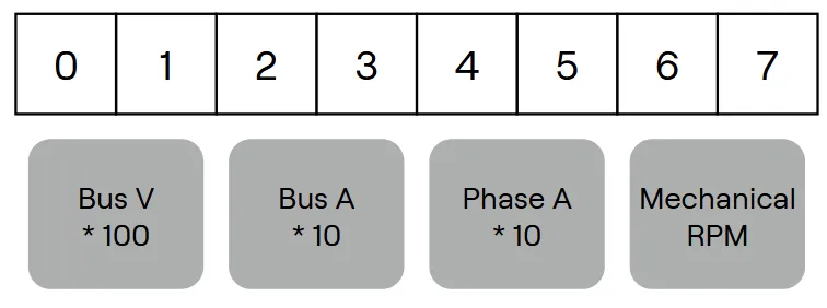
The CAN payload is structured as follows:
Bytes | Datatype | Content |
|---|---|---|
0-1 | INT16 | Bus Voltage (V) * 100 |
2-3 | INT16 | Bus Current (A) * 10 |
4-5 | INT16 | Phase Current (A) * 10 |
6-7 | UINT16 | Mechanical RPM |
ESC Status 2
The ESC Status 2 telemetry broadcast is sent by each ESC at a configurable frequency, default 10Hz.
CAN ID - 0x08586600 | (SID << 2)
The ESC Status 2 message CAN ID is: 0x08586600 | (SID << 2)
Where SID is the SID of the device sending the message.
For SID 1 the CAN ID is: 0x08586604
Advanced:
FID | CFC | CID |
|---|---|---|
Device (Default 11) | 51 | Device SID |
CAN Payload
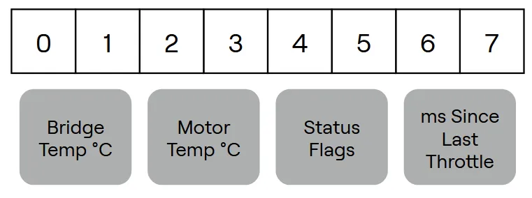
The CAN payload is structured as follows:
Bytes | Datatype | Content |
|---|---|---|
0-1 | INT16 | Bridge Temperature (°C) |
2-3 | INT16 | Motor Temperature (°C) |
4-5 | UINT16 | Status Flags |
6-7 | UINT16 | Milliseconds (ms) since last throttle command |
Status Flags
The status flags field of the ESC Status 2 message is a bitfield, where each bit corresponds to a flag indicating device state. The flag mapping is below.
Bit Position | Flag |
|---|---|
0 | Motor Armed |
1 | Motor Running |
2 | Over Temperature Error |
3 | Bus Over-Current Error |
4 | Phase Over-Current Error |
5 | Bus Over-Voltage Error |
6 | Bus Under-Voltage Error |
7 | Voltage Ripple Error |
8 | Signal Loss Error |
9 | Motor Saturated Error |
10 | Motor Over-Temperature Error |
11 | RPM Limit Reached Error |
12 | Device In Error State |
13 | Output Shorted Error |
14 | Startup Checks Failed Error |
ESC Status 3
The ESC Status 3 telemetry broadcast is sent by each ESC at a configurable frequency, default 10Hz.
CAN ID - 0x08586800 | (SID << 2)
The ESC Status 3 message CAN ID is: 0x08586800 | (SID << 2)
Where SID is the SID of the device sending the message.
For SID 1 the CAN ID is: 0x08586804
Advanced:
FID | CFC | CID |
|---|---|---|
Device (Default 11) | 52 | Device SID |
CAN Payload
The CAN payload is structured as follows:
Bytes | Datatype | Content |
|---|---|---|
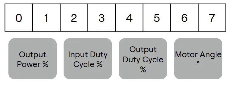
0-1 | INT16 | Output Power Percentage (relative to configured voltage and current limits) |
2-3 | INT16 | Input Duty Cycle Percentage |
4-5 | INT16 | Output Duty Cycle Percentage |
6-7 | INT16 | Motor Angle (Degrees) |