Drive Modes
Drive modes define how the unit transforms and responds to input throttle commands. Different drive modes have different typical use cases.
Normal Rotation Direction
The normal direction is the rotation direction that positive throttle values will command. The normal rotation direction should be set properly to ensure the drive modes function correctly. This is usually done through 1 of 2 mechanisms.
- Motor Controller Settings → normal rotation setting
- Physically switching 2 of the 3 phase cables
Typical use cases
Below are some typical use cases for each of the drive modes. Drive modes can be used outside of their typical use cases but this may lead to undesired behaviors.
Normal Mode: Multi-rotor, VTOL, propeller flight
Reversible Mode: 3D flight, reverse thrust applications
RPM Mode: Helicopter, swashplate flight, constant speed applications
Normal Mode
Normal mode is the default mode of operation, allowing the motor controller to spin in the normal direction at the input duty cycle. The motor controller will track the input duty cycle as quickly as it can. The allowable duty cycle range is between 0% and 100%. Negative throttle values are treated as zero.
Reversible Mode
Reversible mode is similar to normal mode, but allows the motor controller to target positive and negative duty cycles. The allowed range is between -100% and 100% duty. Positive duty cycle will spin the motor in the normal rotation direction, whereas negative duty cycle will spin in the opposite direction. This mode is useful for applications where reverse thrust is intermittently required.
In order for this mode to function, the motor pole pair and motor KV settings must be set correctly. It may also be necessary to set the minimum duty cycle setting if the motor can’t spin at low duty cycles.
If using PWM signalling please review the Communication Guide
RPM Mode
RPM Mode (Speed Control or Governor Mode) allows the motor controller to maintain a speed within a specified range. This is useful for applications where a constant speed is desired from the motor regardless of the load applied.
When in this mode, input throttle signals are linearly mapped between the minimum and maximum RPM settings. 1% throttle will be close to the minimum RPM, 50% throttle will be half way between minimum and maximum RPM, and 100% throttle will be the maximum RPM.
To target a specific RPM, the minimum and maximum RPMs can be set to the same value, thereby making the entire throttle range be one target RPM.
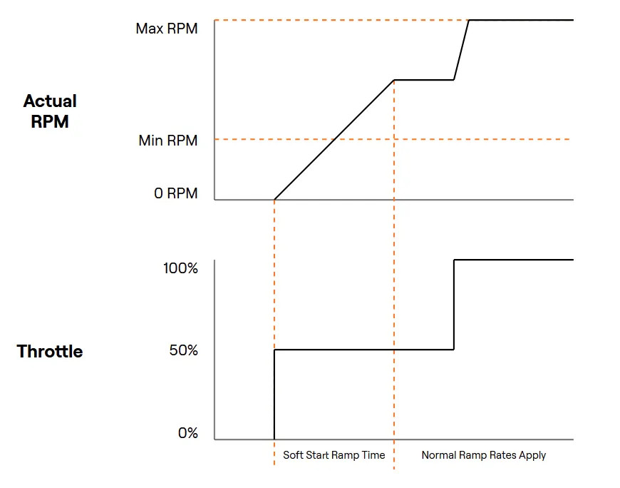
To avoid damaging the drive train, soft start is enabled by default. The motor controller will ramp to the target RPM over the specified amount of time configured in settings.
Motor pole pair count must be set correctly for RPM Mode to be accurate.
Basic RPM Mode Setup:
- Set Drive Mode to RPM
- Set Motor Pole Pairs to the connected motor's number of pole pairs
- Set RPM Mode Minimum to the minimum target RPM
- Set RPM Mode Maximum to the maximum target RPM (can be equal to minimum)
- (Optional) Modify Soft Start Ramp Time to desired spin up speed
Further settings can be found below: